For a long time, Canon has been the number one choice for astrophotography. Given that I’m a Nikon-person, with lots of Nikon gear, spending lot of money on a new Canon camera wasn’t really something I wanted to do. So I bought a cheap Canon camera (1100D), with the fact that I would only ever use it for astrophotography in mind.

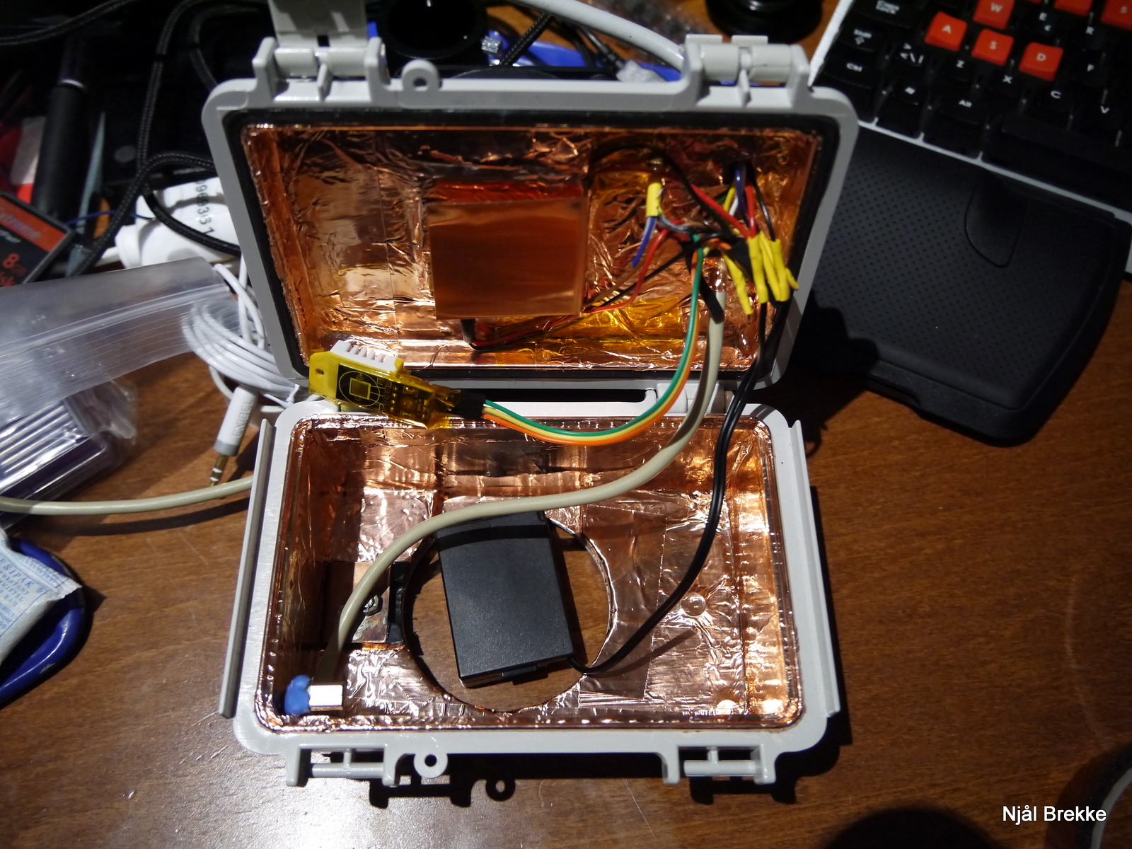
Box with peltier cooled 1100D camera inside, with cables for USB, cooling-control and power.
Rendering it unusable for anything but astrophotography was therefore not something that bothered me, and doing the filter mod was therefore a given. I also figured I might as well try to cool it, in an attempt at decreasing image noise. Also, I like tinkering with stuff, so it would be a win-win. After reading through lots of forum posts, mostly by Gina over at stargazerslounge forum and some camera tests by Gary Honis at his homepage, I figured I would go for the peltier cooling approach. Having already dismantled the camera for the IR-filter mod, the task didn’t seem to daunting.
A peltier (or thermo electric cooling (TEC)), is a semiconductor device which basically works as a heat pump, pumping heat from one side to the other when forcing current through it. For a more detailed description of the equations I used in this article to calculate the peltier effect, look here.
A lot of people were reporting having trouble with condensation on the sensor after cooling, so this was also something I had in mind during the design phase.
Finding the right cooling combination
I started by looking at which peltier element and heatsink would be needed. Peltier elements are named by first stating if it’s a single or double stage peltier (TEC1 or TEC2), the number of semiconductor elements and then the rated maximum current. A single stage, 127 element 3A peltier would therefore be named “TEC1-12703”. It’s therefore easy to find a suitable peltier element on e.g. ebay or deal extreme.
Instead of buying a bunch of peltiers and heatsinks and experimenting with different combinations, I figured a better and cheaper approach would be to try to calculate which peltier element and heatsink combination would be well suited. Using the equations at this page at electonicsdesign.com, I wrote a python script which would plot the sensor temperature at different currents of the peltier element when coupled with a heatsink.
Some parameters were know (peltier and heatsink specs were found in datasheets), other parameters I tried finding by searching and educated guesswork. I read somewhere that when using a external power supply for the camera, the max current draw would be about 200 mA, at 8 volts. This means at a maximum 1.6W of heat would be generated by the camera, only some of it at the sensor. A large (e.g. 70W) peltier element intuitively seemed wrong for cooling down only 1.6W, but I had to do the calculations to prove this. As the temperature difference between what being cooled and the surroundings start to increase, so does the heat transfer from the surroundings as well. How much depends on the thermal insulation in between.
The python script I wrote (available here) would plot the cooling capacity of a peltier element, coupled with a well defined heatsink/fan combination. One big unknown parameter, however, is the thermal insulation between the sensor and the surroundings. Changing this can greatly effect the calculated minimum temperature, and this also shows the impact of isolating the camera/sensor from the ambient temperature. The larger the temperature difference between sensor and ambient, the more heat would be transferred to the sensor (expressed in Watts). This heat would then add to the manageable 1.6W of the camera, effectively limiting the minimum obtainable temperature. The minimum obtainable temperature will therefore be reached when the cooling effect of the peltier equals the heat transfer from the surroundings combined with the heat generated by the sensor.
The following plots shows the theoretical performance of 2A, 3A and 5A peltier elements with a Startech FAN370PRO (copper, low profile 60mm heatsink for CPU’s).
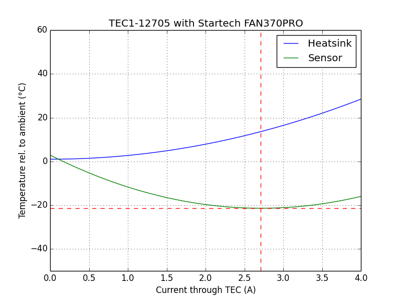

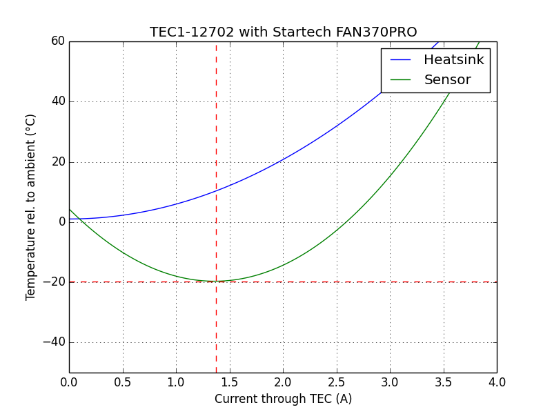
As can be seen from the plots above, running the peltier elements at maximum power will decrease the cooling effect. This is caused by the fact the the cooling effect (temperature difference between hot and cold side) increases linearly with current, while the heat generated by the peltier elements themselves increase as the square of the current. Given a cooler with limited ability to dissipate heat, at a certain point the temperature of the heatsink will rise faster than the temperature difference of the two sides of the peltier, thus increasing the temperature on the cold side.
The difference between the different peltier elements were small. I therefore went for the 2 A version as it would use less power. These calculations are however dependent on the amount of heat transferred to the sensor from the outside world as well, and this coefficient has not been found experimentally. With increasing thermal insulation, the 5A performs a lot worse than the 2A version.
The heatsink were chosen because of it’s small size, good heat conduction (copper) and relativly low weight together with ‘ok’ stated performance. And not to expensive. There is no right combination I would say, just some awful ones and some better depending on the job at hand.
Boxing in the camera
Since condensation could be a problem when cooling, I opted for putting the entire camera inside a air-tight box. The alternative would be to have the thermal finger lead out of the camera (like this), but this would lead to problems with ruggedness, performance and condensation in my view. To minimize the weight and size of the camera, I started removing parts that would not be needed for astro photography:
- Mirror, as this actually adds to vignetting at low F-numbers and would not be used
- Prism and light sensor, useless in a box, consumes space and non-functioning without a mirror
- Autofocus, not working without mirror and also not useful after filter mod and with stars
- Front casing
- Back casing with screen and buttons, not used and obstructing the cold finger
- Top casing with flash, shutter, power and mode selector.
- Flash capacitor. Big and bulky. And flash will never, ever be used.
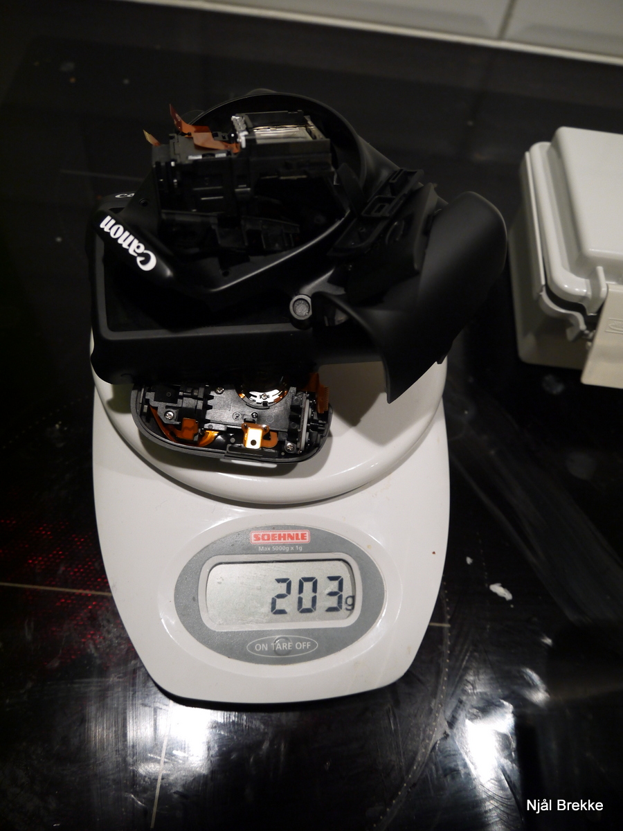
Most of the removed parts, with combined weight of ~200g

The camera after removing most unnecessary parts. Mirror still intact in this image.
With the mirror, autofocus and prism removed, some holes were left in the box in front of the shutter. The hole were the prism had been were covered by an cutout of an old credit card. The top and bottom in front of the shutter were then covered with some black flocking material left over from flocking my telescope.

After mirror were removed, a piece of plastic were glued in place of the focus-screen, with black flocking material applied.

After the autofocus unit were removed, the bottom were also given a treatment of flocking material.
After removing all these parts, and checking that the camera still worked when connected to USB, I started looking for a fitting box. After some searching I found a fitting box (NBF-32304-ND) at digikey, seen below. Utilizing a sealed box, the hope was that I would be able to better control the dew-point of the air inside the box.
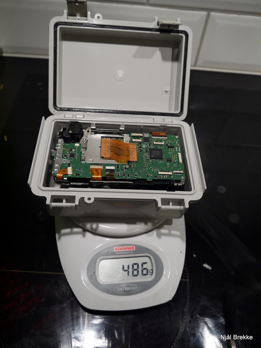
Weighting in at 486 g, more or less the same as the original camera
It was however a very tight fit, width-wise, so I had to solder a usb connector at a 90 degree angle onto the usb cable myself to get it snug enough to fit, as pre-made right angle ones did not fit. After soldering I of course equipped it with some shrink-tubes. The cable would have needed to be cut and soldered anyway, so it could pass through a compression gland.
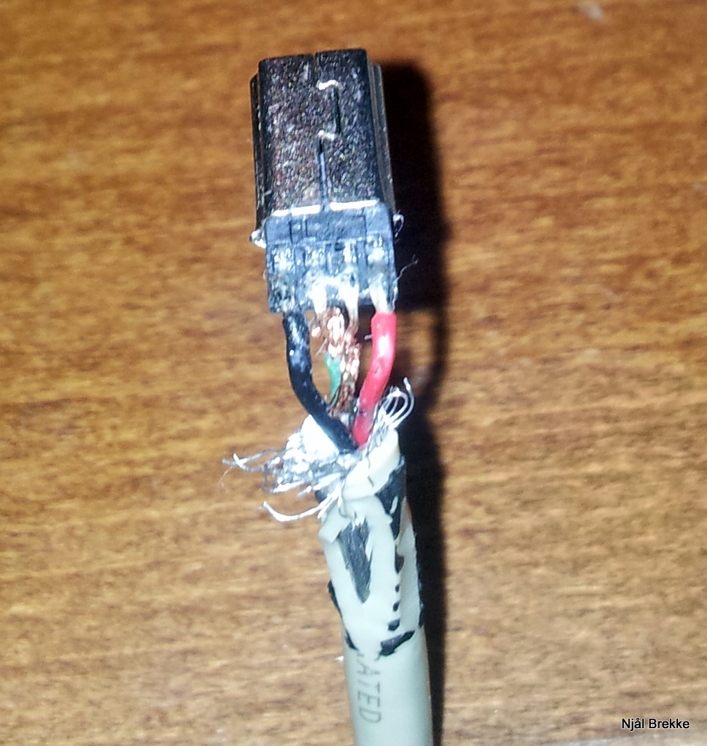
90 degree bend mini-usb connector
A hole were cut in the lid, approximately 5mm larger in both directions than the external dimensions of the peltier element. The heatsink were then centered on top of this, and mounted using both screws in the corners (through the fan) and Tec7 glue, to ensure an air-tight seal. The peltier were then glued using thermal glue to the inside of the lid, directly in contact with the heatsink. A U-shaped copper plate were then glued (also using thermal glue) to the exposed side of the peltier element. A DS18B20 temperature sensor were glued to the copper plate, such that it’s temperature could be measured. The cables into the box (usb + power + sensors) entered through IP44 compression glandsin the lid, next to the heatsink. The IP44 grommets ensured that the box would be air-tight, imaged below.

6mm IP44 Cable glands to prevent moisture to enter the box, and also acting as strain relief for the cables.
6mm Depron were then inserted into the rest of the lid to help on insulating the peltier hot-side from the inside of the box. Depron were also added to the bottom of the box, and by inserting the camera and pressing it down, a small but visible indentation were left in the depron were it had interfaced with the bayonet mount. Using this indentation it was then easy to drill a hole with a diameter slightly (2-3mm) smaller than the bayonet mount, perfectly aligned with the camera when placed in the box. This hole were then carefully sanded until the bayonet ring fitted snugly into it, taking about 1 minute with.
Camera box taped with copper tape, with insulation in top and bottom. Also a small plastic piece can be seen to the left of the bayonet hole, which can be pushed up from the outside, releasing the bayonet lock.
The bayonet mount will (when I think the project is complete) be glued in place to create a good mount and airtight seal, and the camera can then be removed from the box by unscrewing the four bayonet screws. These screws have locktite on them however, and in the end I had to drill two of them out after stripping the socket. No biggie though.
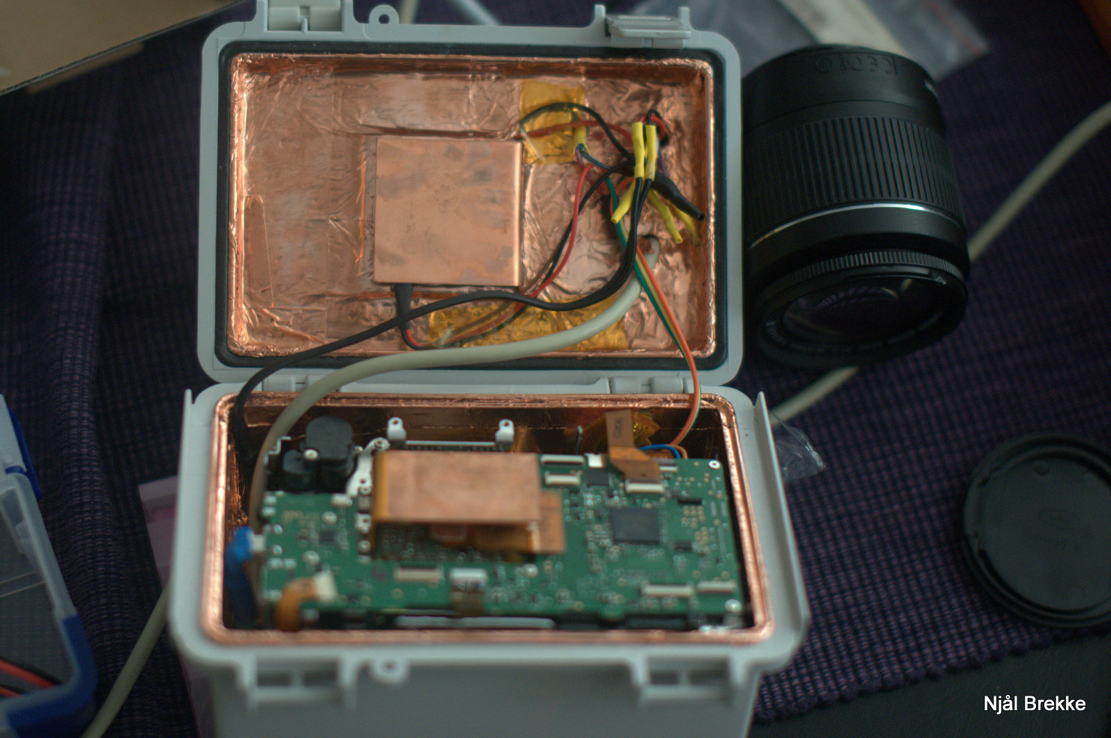
Camera fitted in the camera box, with cold fingers in place.
A layer of copper tape were added to the inside of the box as well (seen above), ensuring that no light would penetrate the plastic, and also hopefully aiding in shielding for EMI. Some conductive gaskets should be added to between the lid and box to ensure a more effective shield without gaps (apart from the light path that is). This copper layer were also connected to the ground and shielding of the cables. And it looks good 🙂
As it is, the camera is not fastened to the box directly, but so far I’ve had no problems of it being loose as it’s a tight fit. As mention earlier however, I will glue the bayonet ring to the box eventually.
Dew prevention
To lower to the dew-temperature, the key is to keep the humidity inside low. Silica gel packs are excellent for keeping the relative humidity stable. Contrary to what I had always though (due to ignorance), these do not absorb moisture through a chemical reaction, but through the topology of the silica beads. Simply adding a silica gel bag into the camera box would only keep the relative humidity somewhat stable while the air temperature would fluctuate, acting as a buffer. This however, would probably not be enough to prevent condensation.
As the silica gel beads are solid (storing water due to their huge surface area) they can be heated to dry them out without damaging the beads. The silica gel were therefore first heated repeatedly in the microwave for about 10-20 s at a time, forcing all the water in it to evaporate. The pack was then inserted into the camera box while still hot (but after it’s stopped steaming). This way, most of the humidity in the air inside the box were absorbed by the silica gel when it started to cool down, before it reached a equilibrium with the surround air inside the box. In the end, the relative humidity ended up at 4%, which ensures a dew-point far, far below the temperature of the sensor, effectively eliminating condensation issues on the sensor. Using an oven is probably a better, safer idea, but of course takes a longer time which matters when you’re excited to see if everything works.
To prevent moist air rushing into the camera box, a lens or filter should always be mounted to the bayonet-mount/t2-ring. Ideally I would not need to open the box to refresh the silica bag at all, but right now once every week or so seems sufficient.
Further camera modifications
Since all camera buttons were removed, the ribbon-cable connecting the upper part of the body to the main PCB were cut, and the mode and power selector were soldered such that the camera would be always on and in manual mode. Power-wires were soldered directly to the battery terminals, such that external power could be used. A small piece of tubing were inserted into the battery-cover switch such that the camera detects this as closed (else, it will not turn on). This can be seen in the two pictures below
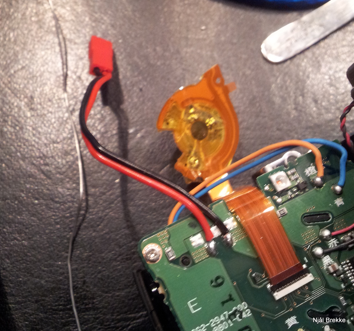
Connector for powering the camera
Soldered so the camera is always on and in M mode.
When cutting the ribbon cable, the camera is no longer able to detect that if the internal flash is closed or whether an external flash is connected to the flash hot-shoe. The result is that the camera believes a flash is connected, limiting the exposure to 1/60s and trying to charge the (now removed) flash capacitor (possibly creating high frequency noise due to the switching nature of the HV power supply). Luckily, instead of further modifying the ribbon cable both flashes can be disabled in the camera menu. It is also possible to disable the flash from the EOS utility from Canon via USB.
I also tested the bias noise measured in images with short exposure, and I could see no difference between using a battery, or an external PWM-based DC-DC converter (which I guess is noisy). The camera mainboard has it’s own power regulators for different voltage rails, and these seems to filter the input power well. The EMI shield around the sensor did not change the noise either.
Cooling
For cooling the sensor directly, a U-shaped copper plate were measured and cut such that it would fit between the CMOS sensor and the PCB the sensor is mounted on. For this I used a 0.7mm copper sheet, and isolated it with kapton tape to prevent short-circuiting the pins beneath the PCB. This was then glued onto the back of the CMOS sensor, again using thermal glue. Thus no movement of the cold finger were possible, and a good thermal connection were ensured.

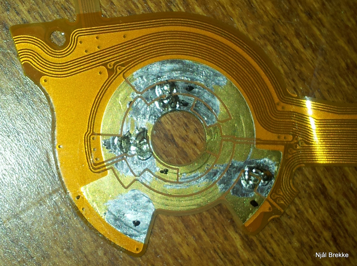
Copper cold finger glued to the sensor, and old plastic card used to seal of the opening for the prism.
Short side-note about using kapton tape to prevent short circuiting the pcb: Does not work. After some testing of the system and the box, the pins on the backside of the sensor PCB went through the kapton tape, hitting the copper cold finger. Thus short circuiting and permanently damaging the PCB mainboard (not the sensor). Luckily I was able to recover the calibration data on the PCB, and ordered a new one from ebay for approx 50 USD. Using a version of Magic Lantern that I modified for the purpose, I restored the calibration data for the sensor and shutter from the old PCB to the new one, basically cloning all settings. After wedging some plastic (from an old credit card) in between the PCBand the copper plate, I was able to ensure that no new short circuit were possible by basically slightly bending the pcb, adding distance between the pins and the cold finger. There has been no problems since, but if I were to redo this mod, I would probably try to file down the pins visible on the back-side of the sensor-PCB.

Cold finger in the lid, and the cold finger mounted to the sensor. When closing the lid, these ensures a good thermal connection. I’ve added a thin (0.5mm) thermal pad to the lid side, to eliminate air-gaps at the interface between the cold fingers.
To regulate the current through the peltier such that a constant temperature could be kept at the sensor, a PID controll-scheme was selected. Implementing a PID controller in arduino was a simple task, and a one-wire DS18B20 temperature sensor were chosen to monitor the temperature of the cold-finger. A DHT-22 one-wire temperatur and humidity sensor were used to calculate the dew-point of the air inside the box, such that the arduino software could limit the sensor temperature to a couple degrees above the dew-point (as a precaution should the relative humidity increase).
The PID controller uses a simple 20×2 LCD to display status, and a rotation encoder to let the user input the desired temperature. The following information is displayed:
- Target temperature
- Sensor temperature
- Inside ambient temperature
- Relative humidity
- Calculated dew-point inside the box
- Peltier power (in % of max)
- Cooling status
- Target temp reached
- Cooling down
- Dew limit reached
The prototype setup (ending up to be the final setup) can be seen in the picture below:
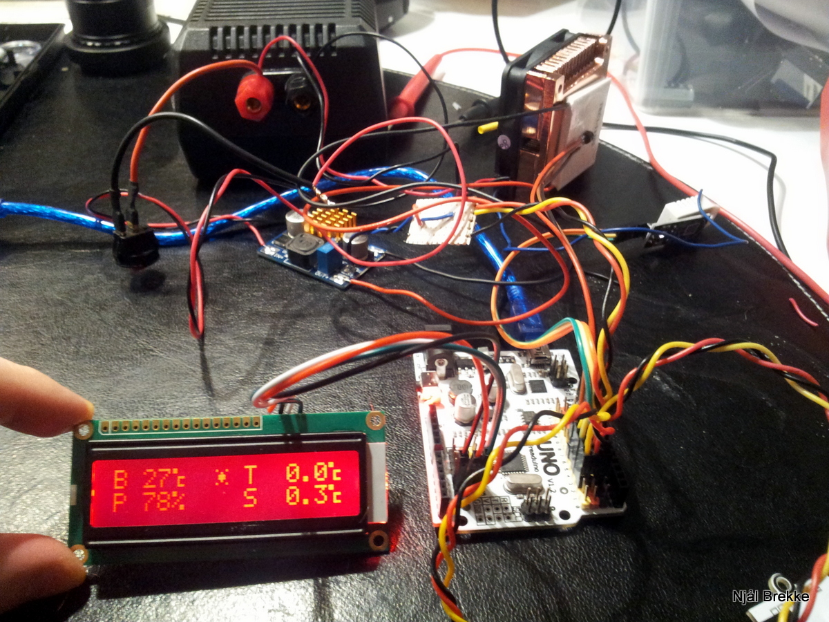
Display, arduino duo, dc-dc converter and peltier+heatsink can be seen.
The output of the PID is sent to the analog output port of the arduino, where it’s output as a PWM signal. This is then passed through an analog low-pass filter into a op-amp configured as a voltage follower. This gives a pure analog DC out signal, with close to zero impedance (for small currents at least). So basically a programmable voltage supply. A DC-DC buck converter bough for about $4 from deal extreme were used to drive the peltier element. Modifying this slightly and connecting the output of the op-amp (through a 820 Ohm resistor) made it possible to control the output voltage of the DC-DC converter between 0 and 12 V using a analog out pin of the arduino. The peltier current (being close to linear in regards to resistance) could then be controlled by controlling the voltage applied over it digitally from the arduino. The output of the PID in software from 0-255 then corresponded to the peltier being completely off to running at maximum power. With the DC-DC converters running at about 90% efficency, this gives the best way to control a peltier element, both in terms of power usage and obtainable minimum temperature.

Arduino controlled DC-DC converter, using a op-amp output as ground signal for the reference pin. The input of the op-amp is the filtered signal from the arduino analog out pins.
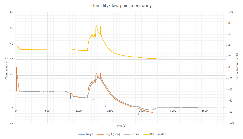
The temperature, humidity etc are all sent over the serial-port of the arduino every second to the computer (if connected) so that the performance and temperature could be monitored. This was usefull when the P, I and D parameters were to be optimized such that a) the target temperature were reached quickly and b) the target temperature were kept without oscillations under changing conditions. Results from some of the tuning attempts can be seen in the image below. The red line shows properly tuned coefficents, while the two other lines shows how the system oscillates when the coefficients are not optimal.

The source code for the Arduino controller can be found here.
Results
By setting the temperature, the PID controller will quickly change the peltier current, and slowly let the sensor reach the desired temperature. The image below shows the temperature curves when the relative humidity were artificially modified by inserting a steaming silica gel pack intro the box.
Under normal operation with the camera imaging, the cooling system is able to cool the camera in excess of 20 °C below the ambient temperature in a couple of minutes.
After adding the silica gel to the box and letting them cool down so it would start absorbing moisture, the humidity in the box were measured to be at 4%. This is really low, keeping the dew-point some 20 °C below the sensor temperature, completely eliminating any chance of dew forming inside the camera. As seen in the image below, with a sensor temperature of -10 °C, the dew point is stable at -36 °C (according to the simplified dew-point calculations done in software anyway).
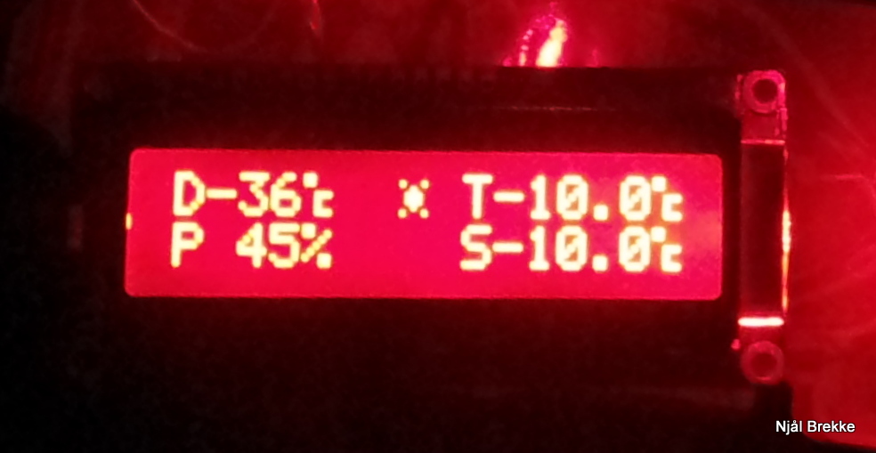
At sensor temperature of -10 °C, the dew-point were calculated to -36 °C. Peltier power at 45%.
Conclusion
In the end, the camera now works great when controlled from BackyardEOS, with a steady temperature. In addition to the benefits in terms of lower image noise, since the temperature can be kept stable at a set level, I do not need to acquire darks each imaging session. By creating a library of darks at different temperatures, ISO values and exposure times, these can be reused.
Next time if you try this mod, DON’T file down the pins on the bottom of the PCB.. those are capacitors and they’re needed for the CMOS to work okay.
I guess you cut out a window in the copper cold finger to accomodate the capacitors there (what I am planning to do)